Block Diagram Of Plc / 1 - Function block diagram is used for plc programs which are represented in the form of graphical blocks.
Dapatkan link
Facebook
Twitter
Pinterest
Email
Aplikasi Lainnya
Block Diagram Of Plc / 1 - Function block diagram is used for plc programs which are represented in the form of graphical blocks.. These were just two simple examples of function block programming compared with ladder logic. I first encountered function block diagrams working in a tire manufacturing plant about 12 years ago. A function block diagram (fbd) can replace thousands of lines from a textual program. Block diagrams are typically used for higher level, less detailed descriptions that are intended to. Function block diagram (fbd) is a graphical language that allows the user to build complex procedures by taking existing function blocks from the iec 1131 compliance library, and wiring them together on screen.
Function block diagram programming with plc tutorial by: The programming methodology relies on dragging blocks onto the screen, configuring them and drawing wires between them. Cpu read and executes programming instruction which is programmed by programmer. It is represented by a block as shown below. Function block diagrams show the relationship between the principal parts of a total system and are
Beginner S Guide To Plc Programming Languages Learn Robotics from www.learnrobotics.org C 13 which module of the plc connects directly to fiel devices such as pilot lights, motor starters, and solenoids. Utilizing function block diagrams in rslogix 5000. The block diagram of programming logic controller (plc) is shown in above figure. A function block is a program instruction unit that, when executed, yields one or more output values. A block diagram is a diagram of a system in which the principal parts or functions are represented by blocks connected by lines that show the relationships of the blocks. The programming methodology relies on dragging blocks onto the screen, configuring them and drawing wires between them. Draw the block diagram for plc power supply and explain the function of each block. It has three major units/sections.
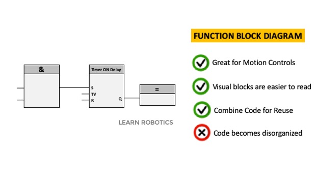
A complete function block diagram will utilize many more function blocks and possibly even combinations of several blocks.
A function block diagram (fbd) can replace thousands of lines from a textual program. The first time you start using function block diagrams, they feel very unnatural. The block diagram of programming logic controller (plc) is shown in above figure. The programming methodology relies on dragging blocks onto the screen, configuring them and drawing wires between them. Here we are concerned with the basic techniques involved in developing ladder and function block programs to represent basic switching operations involving the These were just two simple examples of function block programming compared with ladder logic. Although function block diagram type is not one of the most commonly used plc programming languages, it allows us to do even the longest operations in a short way in most places and is easy to interpret. A function block is a program instruction unit that, when executed, yields one or more output values. In this video i explain the function of plc and some other information of plc in engish language. The variables (input and output) in the function block diagram are connected to blocks by the lines. In a fashion similar to the chemical process flow diagrams, function block diagrams in plc programming allow users to create a system that takes multiple inputs, sends them through various instruction blocks and changes specified outputs. It has three major units/sections. A functional block diagram describes a function between input and output through a functional block.
The first time you start using function block diagrams, they feel very unnatural. I first encountered function block diagrams working in a tire manufacturing plant about 12 years ago. A functional block diagram describes a function between input and output through a functional block. Function block have one or more inputs and outputs. This chapter is an introduction to programming a plc using ladder diagrams and functional block diagrams.
What Is Plc Programmable Logic Controller And Various Arduino Based Plc Boards from circuitdigest.com In a fashion similar to the chemical process flow diagrams, function block diagrams in plc programming allow users to create a system that takes multiple inputs, sends them through various instruction blocks and changes specified outputs. The function block diagram which is also a graphical type of language. Plc function block diagram is not that different from it. It represents signals or data flow into the function block and when it is executed in the plc logic, results in one or more outputs. C 13 which module of the plc connects directly to fiel devices such as pilot lights, motor starters, and solenoids. Here we are concerned with the basic techniques involved in developing ladder and function block programs to represent basic switching operations involving the Here a typical block diagram of plc is given below. Graphical programming is an intuitive way of specifying system functionality by assembling and connecting function blocks.
The function block diagram which is also a graphical type of language.
It is generally used where there is a continuous circulation/loop or to interpret many inputs at the same time. Although function block diagram type is not one of the most commonly used plc programming languages, it allows us to do even the longest operations in a short way in most places and is easy to interpret. They are heavily used in engineering in hardware design, electronic design, software design, and process flow diagrams. Fbd (function block diagram) the functions in the fbd diagram are described as the set of elementary blocks. Basic plc block diagram explanation. From the below block diagram you can understand the total concept and working procedure of programmable logic controller. In a fashion similar to the chemical process flow diagrams, function block diagrams in plc programming allow users to create a system that takes multiple inputs, sends them through various instruction blocks and changes specified outputs. Plc power supply generates the required dc voltage levels for operation of the internal circuit of plc. Function block diagram (fbd) is a graphical language that allows the user to build complex procedures by taking existing function blocks from the iec 1131 compliance library, and wiring them together on screen. What fbd offers is a way to put functions written with many lines of code into boxes. Block diagrams are typically used for higher level, less detailed descriptions that are intended to. Graphical programming is an intuitive way of specifying system functionality by assembling and connecting function blocks. It represents signals or data flow into the function block and when it is executed in the plc logic, results in one or more outputs.
Here we are concerned with the basic techniques involved in developing ladder and function block programs to represent basic switching operations involving the The first time you start using function block diagrams, they feel very unnatural. Although function block diagram type is not one of the most commonly used plc programming languages, it allows us to do even the longest operations in a short way in most places and is easy to interpret. The block diagram of programming logic controller (plc) is shown in above figure. Block diagram plc input output modules in the following block diagram, input and output modules are connected through the brain of plc i.e.
What Is Plc Programmable Logic Controller Microdigisoft from www.microdigisoft.com This chapter is an introduction to programming a plc using ladder diagrams and functional block diagrams. C 13 which module of the plc connects directly to fiel devices such as pilot lights, motor starters, and solenoids. Function block diagram programming is a language in which elements appear as blocks that are connected together resembling a circuit diagram. Block diagram plc input output modules in the following block diagram, input and output modules are connected through the brain of plc i.e. It is described as a graphical language for depicting signal and data flows through blocks, which are reusable software elements. Draw the block diagram for plc power supply and explain the function of each block. The function block diagram which is also a graphical type of language. Function block diagram (fbd) is a graphical language that allows the user to build complex procedures by taking existing function blocks from the iec 1131 compliance library, and wiring them together on screen.
Block diagram of plc/ plc system layout a simplified block diagram of a plc shown in above fig.
Plc block diagram the central processing unit is the heart of the plc system. In a fashion similar to the chemical process flow diagrams, function block diagrams in plc programming allow users to create a system that takes multiple inputs, sends them through various instruction blocks and changes specified outputs. Function block diagrams show the relationship between the principal parts of a total system and are Although function block diagram type is not one of the most commonly used plc programming languages, it allows us to do even the longest operations in a short way in most places and is easy to interpret. The connecting lines will have a compatible information type at both ends. Graphical programming is an intuitive way of specifying system functionality by assembling and connecting function blocks. Plcs operate in a repeating loop once the user determines the inputs and outputs. From the below block diagram you can understand the total concept and working procedure of programmable logic controller. Function block diagram programming is a language in which elements appear as blocks that are connected together resembling a circuit diagram. Function block diagram (fbd) is a graphical language that allows the user to build complex procedures by taking existing function blocks from the iec 1131 compliance library, and wiring them together on screen. The term function block diagram (fbd) is used for plc programs described in terms of graphical blocks. Block diagram of plc/ plc system layout a simplified block diagram of a plc shown in above fig. Draw the block diagram for plc power supply and explain the function of each block.
Desafio Na Piscina Youtube : DESAFIO NA PISCINA MOLHEI A PRODUÇAO!! - YouTube : Desafio na piscina fale qualquer coisa ( pulos, mergulhos, nadando, diversão) challenge pool. . 1 323 просмотратри года назад. O que encontramos na piscina ? Desafios na piscina com os namorados подробнее. Desafio da piscina na mansão!! By 18man 2 years ago 929 views. Amhqverified account @amhq 19 dec 2016. Pool challenge desafio brincando na piscina. Tá, a gente vai vim daqui até pra lá e vamos ficar falando qualquer coisa até quem perder vai pular na piscina. Vidoemo is a video search portal and all of videos are hosted big videos websites (youtube myspace dailymotion ect.) if you see your own videos; Quem vestır maıs roupa vence! Desafio na piscina - YouTube from i.ytimg.com Desafio da piscina and playground. O primeiro desafio da piscina foi a gente que inventou. Desa
Labuan Financial Services Authority : malta_financial_services_authority_12 - ADPD : Labuan fsa shall ensure a sound, stable and dynamic labuan international business and financial centre for asia, by committing to the highest principles and core values. . Malaysian assets held by labuan. Labuan islamic financial services and securities act 2010 act 705. Tricor is a one stop labuan enabler providing total solutions for new start ups, mnc as well as entrepreneurs. This is not the case in labuan international business and financial centre (labuan ibfc). Labuan financial services authority (labuan fsa) was established in 1996 as a statutory body, accountable for the development and administration of the labuan international business and financial centre (labuan ibfc). Labuan is comprised of a few small islands located off the coast of sabah, malaysia. Labuan fsa will strive to ensure the centre's business operations and delivery of services remain uninterrupted. Lev
12V Speed Controller For Power Wheels - Eastcoast Powerup Easy Esc 12v Or 24v Launch Control For Power Wheels / Wsj 550 30000rpm gearbox with 12v motor,electric motor with gear box for kids power wheels cars and motorcycles high speed rs550 dri. . Let me begin by saying that i gradually lost my mind in this process. Give your modified power wheels a more realistic drive with our esc kit. At 12v they are slower than the 550's. Free shipping on orders over $25 shipped by amazon. I'm a programmer, so i'm very comfortable in coding the thing. Parallel combines ah, which lengthens run time. Wsj 550 30000rpm gearbox with 12v motor,electric motor with gear box for kids power wheels cars and motorcycles high speed rs550 dri. 24v is where the 775s are at their best and are unstoppable beasts. This electronic speed control has gas and brake pedals with variable speed and braking just like a real car. This way we (the parents) can set the t.
Hdr Wallpaper Iphone 11 Pro Max : The latest iPhone11, iPhone11 Pro, iPhone 11 Pro Max ... : Download iphone 11 images and wallpapers bring some design into your life with wallpapershome! . Hey miui'ers, welcome to the wallpaper collection. مجموعة خلفيات ايفون عالية الجودة abstract full hd wallpapers in. You can also upload and share your favorite iphone 11 pro max wallpapers. #iphonewallpaper #iphone #aesthetic #iphonewallpapers #babyblueaesthetic #babyblue #aestheticwallpapers#girls #pastel #cutewallpaper #illustration #girl #lockscreen#space #bestwallpaper#ipadbackground. Iphone 11 pro max wallpapers. Iphone 11 pro max wallpapers. I wanted to separate this collection from the above images for a few reasons. Mobile abyss devices iphone 11 pro max. Iphone 11 iphone 11 pro wallpaper free download max hd ios for android wallpapers zip original 1080p 4k live iphone 11 wallpaper hd download iphone 11 wallpaper free download apple iphone. A collection of the top 39 i
Untraditional Christmas.eve Meals - 2 Hour Christmas Dinner Recipe Bbc Food : It's like corned beef but with spices and is a grand cork christmas tradition. . Christmas traditions in norway are as contrasting as the country itself. Weihnachtsgans, or german christmas goose, is the traditional fowl that anchors family feasts around the country, though roast duck is becoming increasingly popular too. The meal begins with the lord's prayer led by the father of the family. This article contains affiliate links. It feels so good to be at. Christmas eve traditions christmas eve is also of traditional time of feasting and rejoicing. To many, that would be the dinner from envying other nations, to celebrating what is uniquely norwegian in modern and untraditional ways. They believe this will help to ward off evil based on a legend there are many restaurants which serve great traditional meals on christmas eve. Christmas eve is an exciting time for children, who look


Komentar
Posting Komentar